Lecture - 7 ( jet strikes on moving curved plates )
Similarly after entering water will deflect by angle δ and exit from point 2 and at exit Vr2 will make angle φ as shown in below figure.
Now water coming out of nozzle at angle α with velocity vector V1 and split into sin and Cos component. The cos component of this vector V1 or we can say V1 cosα is known as whirl velocity at entry point and denoted by Vw1. Whereas sin component of this vector V1 or we can say V1 sinα is known as flow velocity at inlet and denoted as Vf1.
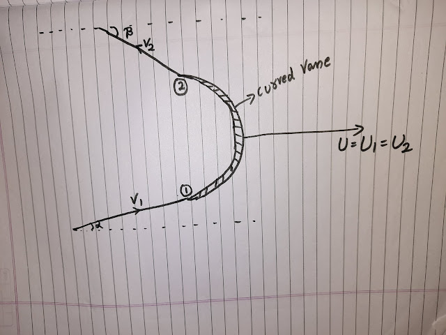
We are using all our same previous notations, the only difference is that in this case curved plate is there and jet is striking at the tip of this moving curved vane.
V1 is the velocity of water jet with respect to ground entering at the tip of moving curved vane making angle α with horizontal axis. Water jet enter vane at entry point 1 and get deflected by δ angle and exit as velocity V2 m/sec making angle 'β' with horizontal axis. This curved vane is moving with velocity 'U' as shown in below figure.
V1 is the velocity of water jet with respect to ground entering at the tip of moving curved vane making angle α with horizontal axis. Water jet enter vane at entry point 1 and get deflected by δ angle and exit as velocity V2 m/sec making angle 'β' with horizontal axis. This curved vane is moving with velocity 'U' as shown in below figure.
Now first of all let me draw a parallel vector U1 on entry and U2 at exit. After that as we know V1 is the water Jet velocity entering on vane with respect to ground and vane is moving with velocity U1, so the relative velocity of water Vr1 (velocity with respect to blade) will never enter the vane with angle α. Entering angle of both the velocity vector V1 and Vr1 is not same, so they are not collinear vector. Vr1 will enter the vane tangentially for smooth flow making angle θ with horizontal axis as shown in below figure.
Now we got our velocity triangle at inlet. Similarly velocity triangle at outlet can be drawn. Vw2 denotes whirl velocity at exit and Vf2 denotes flow velocity at exit. From this figure we can also conclude that δ+θ+φ=180⁰
Now let us calculate the force in X and Y direction, by considering our observer be outside power calculation will become absolute.
We know actual mass flow rate entering is m=ρ*a*Vr1
Fx = force in X direction or horizontal direction = m*V1cosα - m*(-V2cosβ) =m*Vw1 + m*Vw2 = m(Vw1+Vw2) Newton
Fy = force in Y direction or vertical direction = m*V1sinα - m*V2sinβ = m(Vf1 - Vf2) Newton
If vane is symmetrical than θ=φ
Here we can also calculate work done. Actually work done per second because we have mass flow rate kg/sec so we will get work done per second which is also called as power.
Power = workdone per second = Fx * U = m(Vw1+Vw2)U


Comments
Post a Comment