Posts

Showing posts with the label Theory of machies

Lecture - 15 (Mechanical advantage, mechanism efficiency, toggle mechanism)

Image
Mechanical advantage   It is defined as the ratio of the force produced by a machine to the force applied to it, used in assessing the performance of machine.  The combination of pulley system is shown in the below figure-  Here for lifting download F force is required but the effort given to the system is 8 times less, which is the good example of mechanical advantage. For the above system mechanical advantage is 8 Mechanical advantage = load / effort  Mechanical advantage for linear motion is -  Mechanical advantage for angular motion is -  Efficiency of system or mechanism Efficiency of the system is defined as the ratio of output power to the input power. PROBLEM - Find out mechanical advantage of the given mechanism having 100% efficiency. Solution -  In the sense of angular velocity It means that above mechanism is toogle mechanism.  Toggle mechanism   Those mechanism whose mechan...
Lecture - 14 ( double slider crank mechanism)

Image
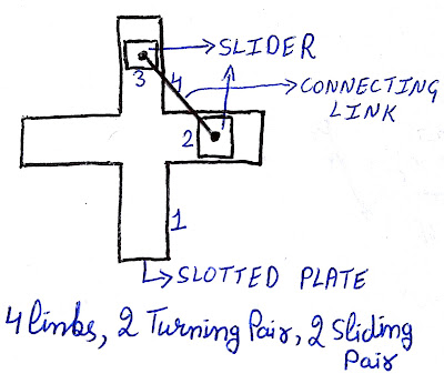
DOUBLE SLIDER CRANK MECHANISM   Double slider crank mechanism is a combination of four links having two turning pairs and two sliding pairs. Diagram of this mechanism is shown below- This mechanism consists of three inversions as listed below- First inversion (fixed slotted plate) Second inversion (fixed slider) Third inversion (fixed connecting rod) First inversion    When slotted plate is fixed then it become the first inversion of double slider crank mechanism. Its example is elliptical trammel. Diagram of elliptical trammel is shown below-  An electrical trammel is a simple mechanism which can trace exact elliptical path. It consists of two shuttles which are are confined to perpendicular channels or Rails, and a rod which is attached to shuttles by pivots at fixed position along the rod. As shuttle moves back and forth, each along its channel, the end of the rod moves in an elliptical path. Elliptical trammel is used in aut...

Lecture - 13 ( single slider crank mechanism (part-2))

Image
Third inversion   In 3rd inversion of single slider crank mechanism connecting rod is fixed. Examples - crank & slotted Lever quick return motion mechanism, oscillating cylinder engine mechanism. CRANK AND SLOTTED LEVER QUICK RETURN MOTION MECHANISM-   In this mechanism input is in the form of rotation and output is in the form of oscillation. Brief diagram of mechanism is shown below According to figure link1 (CA) is connecting rod of mechanism which is fixed. Link 2 is crank which is in rotation motion. Link 3 is slider which is placed inside slotted bar. Link 4 of mechanism is slotted bar. Let us consider'β' is the cutting stroke angle and ' α'  is return stroke angle. Time required in cutting stroke angle will be more than time required in return stroke angle, therefore it is quick return motion mechanism .As shown in figure value of ' α'  is less than value of ' β'  because of quick return motion mechanism. Quick retu...

Lecture - 12 (Single slider crank mechanism (part -1))

Image
SINGLE-SLIDER CRANK MECHANISM   Single slider crank mechanism consist of four links, three turning pairs and one sliding pair. It was developed by sir James Watt.  It has four inversions which are listed below -  First inversion (fixed cylinder) Second inversion (fixed crank) Third inversion (fixed connecting rod) Fourth inversion (fixed slider) First inversion -    In first inversion cylinder will be fixed. It is also called basic inversion. Examples -  In the figure shown below mechanism of internal combustion engine is there. Here link 1 (cylinder) is fixed, link 2 (crank) is in rotation, link 3 (connecting rod) is in general motion and link 4 (piston) is in sliding motion. In this case piston is our input and Crank is our output, which means we are giving reciprocation as input and getting rotation as output. This mechanism can be used in opposite direction also and in that case this mechanism become a compressor. I...

Lecture - 11 (Transmission angle in four bar mechanism)

Image
The angle between coupler link and output link in four bar mechanism is known as transmission angle. It is represented as ' μ'.   In the given figure Let us consider angle between link AO and link OC (fixed link) is represented by ' θ'.   Let us consider length of link OC is 'a', length of link OA is 'b', length of AB is 'c' and length of BC is 'd'.  According to law of cosine we get -  Now  μ will be different for different values of  θ. μ will be maximum for  θ = 180 degrees  & minimum for  θ = 0 degrees.   Problem 1-  Calculate maximum and minimum value of transmission angle for the following mechanism. Length of link OC is 5cm, length of link AO is 1cm, length of link AB is 4cm and length of link BC is 3cm. Solution 1 -   To calculate minimum value of transmission angle observe the mechanism when  θ = 0 degrees   To calculate maximum value of transmission angle observe the mechani...

Lecture - 10 ( four bar mechanism and grashof's law)

Image
Inversions of mechanisms  Different mechanisms can be obtained by fixing different-different links of the same kinematic chain. These are called as inversions of the mechanism.  By changing the fixed link, the number of mechanisms which can be obtained is equal to the number of links. The inversion of a mechanism does not change the motion of its links relative to each other. Remember if number of links are 'L' than the number of inversions will be less than or equal to 'L' . FOUR BAR MECHANISM   This mechanism consist of 4 links and 4 turning pairs.  One of the most useful and most common mechanisms is the four-bar linkage. In this mechanism, the link which can make complete rotation is known as crank. The link which oscillates is known as rocker or lever. The link connecting these two is known as coupler and the link which is stationary is known as fixed link. Four bar mechanism is also called as Quadratic cycle mechanism. Example is shown ...

Lecture - 9 ( Grubler's approach and simple mechanism)

Image
GRUBLER'S EQUATION Grubler explain that to convert any linkage combination in a Kinematic chain or constrained motion mechanism, the following equation must be satisfy     3L - 2J - 4 = 0    This explanation is given for those mechanism whose degrees of freedom is one (F=1) and having no higher pairs (H=0). If we apply Grubler's conditions in KUTZBACH equation we get Grubler's equation. F = 3(L-1) - 2J - H ; (KUTZBACH equation) now apply Grubler's conditions (F=1, H=0) 1 = 3(L-1) - 2J - 0 0 = 3L - 2J - 4 ; (GRUBLER'S EQUATION) Grubler's equation is derived from KUTZBACH equation after applying certain conditions, therefore Grubler's equation is also called as modified Kutzbach equation. CONCLUSION OF GRUBLER'S APPROACH As we know for making a mechanism, Grubler's equation must be satisfied.We know the term of grubler's equation '-2J - 4' will always be even for each value of 'J'. To satisfy the...

Lecture - 8 ( problems on degrees of freedom)

Image
PROBLEM 1  - For the mechanism shown in figure, calculate it's degrees of freedom (F) SOLUTION 1  -  number of links (L) = 8 Number of binary joints (J) = 10 Number of higher pair (H) = 0 Number of those motions which are not the part of mechanism (N) = 0 KUTZBACH equation: F=3(L-1) - 2(J) - H - N F = 3(8-1) - 2(10) - 0 - 0 = 1 F = 1  PROBLEM 2 -  Calculate degrees of freedom for given mechanism SOLUTION 2 -   L = 4 ; J = 3 ; H = 1 ; N = 1 F = 3(L-1) - 2J - H - N = 3(4-1) -2(3) -1 -1 = 1 F = 1    PROBLEM 3 -  Calculate degrees of freedom for given mechanism.  SOLUTION 3 -   L = 5 ; H = 1 ; J = 5 ; N = 0 F = 3(5-1) -2(5) - 1 - 0 = 1  F = 1 PROBLEM 4 -  Calculate degrees of freedom for given mechanism SOLUTION 4 -    Here one link is spring. Spring is the link of flexible length. Spring can be replaced by 2 links connected with turning pair. ...